- 您现在的位置:买卖IC网 > Sheet目录3890 > PIC18C858T-E/PT (Microchip Technology)IC MCU OTP 16KX16 CAN 80TQFP
2000 Microchip Technology Inc.
Advanced Information
DS30475A-page 127
PIC18CXX8
14.0
CAPTURE/COMPARE/PWM
(CCP) MODULES
Each CCP (Capture/Compare/PWM) module contains
a 16-bit register that can operate as a 16-bit capture
register, as a 16-bit compare register, or as a PWM
Duty Cycle register. Table 14-1 shows the timer
resources of the CCP module modes.
The operation of CCP1 is identical to that of CCP2, with
the exception of the special event trigger and the CAN
message timestamp received. (Refer to “CAN Module”,
Section 17.0 for CAN operation.) Therefore, operation
of a CCP module in the following sections is described
with respect to CCP1.
Table 14-2 shows the interaction of the CCP modules.
Register 14-1 shows the CCPx Control registers
(CCPxCON). For the CCP1 module, the register is
called CCP1CON and for the CCP2 module, the regis-
ter is called CCP2CON.
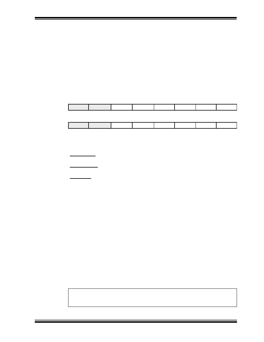
REGISTER 14-1: CCP1CON REGISTER
CCP2CON REGISTER
U-0
R/W-0
CCP1CON
—
DC1B1
DC1B0
CCP1M3
CCP1M2
CCP1M1
CCP1M0
bit 7
bit 0
U-0
R/W-0
CCP2CON
—
DC2B1
DC2B0
CCP2M3
CCP2M2
CCP2M1
CCP2M0
bit 7
bit 0
bit 7-6
Unimplemented: Read as '0'
bit 5-4
DCxB1:DCxB0: PWM Duty Cycle bit1 and bit0
Capture Mode:
Unused
Compare Mode:
Unused
PWM Mode:
These bits are the two LSbs (bit1 and bit0) of the 10-bit PWM duty cycle. The upper eight bits
(DCx9:DCx2) of the duty cycle are found in CCPRxL.
bit 3-0
CCPxM3:CCPxM0: CCPx Mode Select bits
0000
= Capture/Compare/PWM off (resets CCPx module)
0001
= Reserved
0010
= Compare mode, toggle output on match (CCPxIF bit is set)
0011
= Capture mode, CAN message received (CCP1 only)
0100
= Capture mode, every falling edge
0101
= Capture mode, every rising edge
0110
= Capture mode, every 4th rising edge
0111
= Capture mode, every 16th rising edge
1000
= Compare mode,
Initialize CCP pin Low, on compare match force CCP pin High (CCPIF bit is set)
1001
= Compare mode,
Initialize CCP pin High, on compare match force CCP pin Low (CCPIF bit is set)
1010
= Compare mode,
Generate software interrupt on compare match
(CCPIF bit is set, CCP pin is unaffected)
1011
= Compare mode,
Trigger special event (CCPIF bit is set, reset TMR1 or TMR3)
11xx
=PWM mode
Legend:
R = Readable bit
W = Writable bit
U = Unimplemented bit, read as ‘0’
- n = Value at POR
’1’ = Bit is set
’0’ = Bit is cleared
x = Bit is unknown
发布紧急采购,3分钟左右您将得到回复。
相关PDF资料
PIC18C858T-I/PT
IC MCU OTP 16KX16 CAN 80TQFP
PIC18C658T-I/PT
IC MCU OTP 16KX16 CAN 64TQFP
PIC16LC717T-E/SS
IC MCU OTP 2KX14 A/D PWM 20SSOP
PIC16LC771T/SO
IC MCU OTP 4KX14 A/D PWM 20SOIC
PIC16LC771T-E/SO
IC MCU OTP 4KX14 A/D PWM 20SOIC
PIC16C771T-E/SO
IC MCU OTP 4KX14 A/D PWM 20SOIC
PIC16LC770T/SS
IC MCU OTP 2KX14 A/D PWM 20SSOP
PIC16LC717T-I/SO
IC MCU OTP 2KX14 A/D PWM 18SOIC
相关代理商/技术参数
PIC18C858T-I/L
功能描述:8位微控制器 -MCU 40MHz 16K OTP RoHS:否 制造商:Silicon Labs 核心:8051 处理器系列:C8051F39x 数据总线宽度:8 bit 最大时钟频率:50 MHz 程序存储器大小:16 KB 数据 RAM 大小:1 KB 片上 ADC:Yes 工作电源电压:1.8 V to 3.6 V 工作温度范围:- 40 C to + 105 C 封装 / 箱体:QFN-20 安装风格:SMD/SMT
PIC18C858T-I/PT
功能描述:8位微控制器 -MCU 32KB 1536 RAM 68I/O RoHS:否 制造商:Silicon Labs 核心:8051 处理器系列:C8051F39x 数据总线宽度:8 bit 最大时钟频率:50 MHz 程序存储器大小:16 KB 数据 RAM 大小:1 KB 片上 ADC:Yes 工作电源电压:1.8 V to 3.6 V 工作温度范围:- 40 C to + 105 C 封装 / 箱体:QFN-20 安装风格:SMD/SMT
PIC18F1220-E/ML
功能描述:8位微控制器 -MCU 4KB 256 RAM 16 I/O RoHS:否 制造商:Silicon Labs 核心:8051 处理器系列:C8051F39x 数据总线宽度:8 bit 最大时钟频率:50 MHz 程序存储器大小:16 KB 数据 RAM 大小:1 KB 片上 ADC:Yes 工作电源电压:1.8 V to 3.6 V 工作温度范围:- 40 C to + 105 C 封装 / 箱体:QFN-20 安装风格:SMD/SMT
PIC18F1220-E/P
功能描述:8位微控制器 -MCU 4KB 256 RAM 16 I/O RoHS:否 制造商:Silicon Labs 核心:8051 处理器系列:C8051F39x 数据总线宽度:8 bit 最大时钟频率:50 MHz 程序存储器大小:16 KB 数据 RAM 大小:1 KB 片上 ADC:Yes 工作电源电压:1.8 V to 3.6 V 工作温度范围:- 40 C to + 105 C 封装 / 箱体:QFN-20 安装风格:SMD/SMT
PIC18F1220-E/SO
功能描述:8位微控制器 -MCU 4KB 256 RAM 16 I/O RoHS:否 制造商:Silicon Labs 核心:8051 处理器系列:C8051F39x 数据总线宽度:8 bit 最大时钟频率:50 MHz 程序存储器大小:16 KB 数据 RAM 大小:1 KB 片上 ADC:Yes 工作电源电压:1.8 V to 3.6 V 工作温度范围:- 40 C to + 105 C 封装 / 箱体:QFN-20 安装风格:SMD/SMT
PIC18F1220-E/SS
功能描述:8位微控制器 -MCU 4KB 256 RAM 16 I/O RoHS:否 制造商:Silicon Labs 核心:8051 处理器系列:C8051F39x 数据总线宽度:8 bit 最大时钟频率:50 MHz 程序存储器大小:16 KB 数据 RAM 大小:1 KB 片上 ADC:Yes 工作电源电压:1.8 V to 3.6 V 工作温度范围:- 40 C to + 105 C 封装 / 箱体:QFN-20 安装风格:SMD/SMT
PIC18F1220-H/ML
功能描述:8位微控制器 -MCU 4KB FL 256RAM 16 I/O RoHS:否 制造商:Silicon Labs 核心:8051 处理器系列:C8051F39x 数据总线宽度:8 bit 最大时钟频率:50 MHz 程序存储器大小:16 KB 数据 RAM 大小:1 KB 片上 ADC:Yes 工作电源电压:1.8 V to 3.6 V 工作温度范围:- 40 C to + 105 C 封装 / 箱体:QFN-20 安装风格:SMD/SMT
PIC18F1220-H/P
功能描述:8位微控制器 -MCU 4KB FL 256RAM 16 I/O RoHS:否 制造商:Silicon Labs 核心:8051 处理器系列:C8051F39x 数据总线宽度:8 bit 最大时钟频率:50 MHz 程序存储器大小:16 KB 数据 RAM 大小:1 KB 片上 ADC:Yes 工作电源电压:1.8 V to 3.6 V 工作温度范围:- 40 C to + 105 C 封装 / 箱体:QFN-20 安装风格:SMD/SMT